
Electric network model validation is the testing of GIS network data before it feeds an OMS or ADMS. Before go-live, check that every asset traces to a source, phases and voltages are right, open points match the field, customers link to the right transformer and CIM exports load cleanly. Then prove it with system tests and agreed sign-off rules.
- Check connectivity first, because every later test depends on a network that traces correctly.
- Phase and voltage errors are hard to see on a map, so find them with rules and traces.
- One wrong normally open point can merge or split feeders, so check every switch state.
- Customer links drive outage prediction, so measure how many exist and how many are right.
- Agree sign-off rules early, and keep the checks running after go-live as the network changes.
Why does an electric network model need checks before go-live?
Checks prove that the GIS model behaves like the real network. That matters because an outage management system (OMS) or an advanced distribution management system (ADMS) traces and switches on that model. So data errors become control room errors on day one.
Our explainer on geospatial electric network modelling shows how the model is built. This article is the next step. It lists what to test before the model goes live, and how to decide it is ready.
Poor data also has a real cost. For example, a US National Renewable Energy Laboratory paper notes that better data quality can account for up to 25% of ADMS deployment costs. In addition, clean data does not stay clean. New assets arrive each week, and so do new errors.
So treat electric network model validation as a gated stage with owners, rules and proof. It is not a quick look at the map.
How do you check connectivity and topology in a GIS network model?
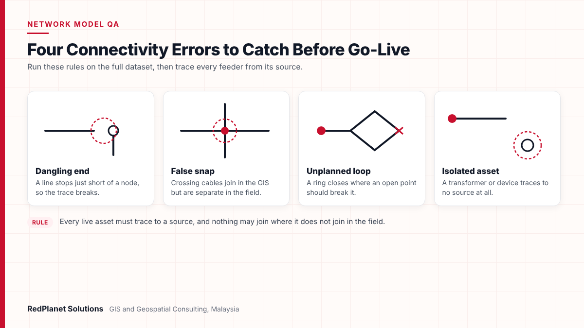
Start with connectivity, because every other test relies on tracing. The goal is simple. Every live asset should trace back to a source, and nothing should join where it does not join in the field.
First, run a full trace from each feeder breaker. Then compare the result with the feeder register and with field knowledge. If the trace cannot reach an asset, flag it. Next, run rules across the whole dataset, not just a sample.
- Isolated assets: lines, transformers or devices that trace to no source.
- Dangling ends: line ends that stop just short of a node, so the trace breaks.
- False snaps: crossings that join in the GIS but are separate in the field.
- Unplanned loops: closed rings that should instead break at an open point.
- Feeder mixing: one asset fed from two feeders while all switches are normal.
- Substation links: busbars, breakers and transformer bays joined in the right order.
Also compare the map with a schematic view. For instance, an automated schematising service quickly shows faults that hide on a busy street map.
If more than a small share of assets fail the source trace, stop and fix the data first. Later checks on a broken network waste effort, because the results will change once the links are fixed.
What phasing and voltage checks catch the most model errors?
Phase and voltage checks confirm that power can flow the way the model says. But these errors rarely show on a map, so you need rules and traces to find them.
Phase data matters most for load flow, single-phase outages and fault location. Voltage data matters for every trace that crosses a transformer. For instance, an 11 kV line joined straight to a 400 V service line breaks a clear rule. However, a wrong phase label on a side branch can look quite normal.
| Check | Rule | Common cause |
|---|---|---|
| Phase flow. | No phase appears that the line above lacks. | Side branch tagged ABC. |
| Device phase. | Switch phase matches its line. | Default value used. |
| Transformer phase. | It sits on a phase that exists. | Phase not captured. |
| Voltage step. | Voltage changes only at a transformer. | Wrong class on a new line. |
| Voltage zone. | One traced zone has one voltage. | Fields copied from another feeder. |
Then compare phase totals with field or meter data where you have it. As a result, you test the data against the real network, not only against itself. If gaps remain, log them as known issues with an owner and a fix date.
How should normally open points and device states be checked?
Device states set where one feeder ends and the next begins. Therefore, every switch, breaker and fuse needs the right normal state before the model goes live.
One wrong normally open point can merge two feeders, or split one feeder in two. In an OMS, that changes which customers sit under a predicted outage. In an ADMS, it also changes load flow results and switching plans.
- Confirm that every open point appears in the approved switching register.
- Then check that each feeder has one source under normal state.
- Store normal state and current state apart, so staff can switch without editing the design.
- Review device types and ratings, because isolation logic depends on them.
- Test that control room switching does not overwrite the GIS normal state.
In our experience, most go-live surprises trace back to device states rather than geometry. A map can look perfect but still feed the wrong customers if one open point is wrong.RedPlanet Solutions
Finally, ask control room staff to walk through the normal state on a few feeders. They often spot issues that rules alone miss.
How do you check customer-to-transformer links and missing data?
Customer links tie each meter to the transformer and phase that supplies it. Outage prediction depends on them, so measure both coverage and accuracy before system tests start.
Coverage is the share of active accounts linked to a transformer. Accuracy is whether those links are right. You can check coverage with a simple query against the billing extract. But accuracy needs samples, field checks or meter event data.
Link coverage
Every active account links to one service point and also one transformer.
Link accuracy
Sampled links match field or meter data, so check feeder edges with care.
Critical customers
Hospitals, life support and priority sites link correctly and carry the right flags.
Required fields
Device type, rating, phase, voltage, status and asset ID hold real values rather than blanks.
Default audit
Count placeholder values, because an ADMS needs device-specific data.
Missing fields need the same care. First, define which fields each system needs. Then report gaps by feeder. In addition, flag default values, since a generic transformer rating will pass a blank check but still give wrong load results.
In Malaysia, customer records count as personal data under the Personal Data Protection Act 2010. So mask customer details in test systems and shared reports. Also, structured GIS QA/QC makes these checks repeatable rather than one-off.
What should you check in a CIM export before go-live?
A CIM export check confirms that the model survives the move into the format the OMS or ADMS reads. Many utilities share network models in the IEC Common Information Model, so the file must match the agreed profile.
Which IEC standards apply?
The base CIM sits in IEC 61970-301. Then IEC 61968-11 adds the distribution extensions to that base. Next, IEC 61968-13, now in a second edition from 2021, sets profiles for sharing balanced and unbalanced distribution models. Finally, IEC 61970-552 sets the CIMXML file format and its rules.
- Profile check: the file passes against the profile version the vendor expects.
- Object counts: lines, switches, transformers and service points still match the GIS.
- Stable IDs: asset IDs persist between exports, so updates do not create duplicates.
- Export topology: terminals and nodes rebuild the same traces as the GIS, so nothing is lost.
- Round trip: load the file into the target system, then compare traces feeder by feeder.
Also agree the CIM profile version and any vendor extensions in writing. If versions differ, the load often fails late. Tools such as FME can compare counts and run rule checks between the GIS and the export.
Which OMS and ADMS tests should run before cut-over?
System tests prove that the checked model works inside the OMS or ADMS. Data checks are needed, but only scenario tests show how the system will act during a real event.
Plan these tests with operators, not only with the GIS team. Then run each scenario on a mix of feeders: urban cable, rural overhead and mixed networks. For example, a rural feeder with long single-phase spurs will expose phase errors that an urban cable network may hide.
- Model load: full and partial loads finish, and then no objects are rejected.
- Trace match: OMS or ADMS traces match GIS traces on every test feeder.
- Outage prediction: if test customers call, the calls roll up to the right device.
- Switching: a planned sequence isolates and restores the expected customers.
- Load flow: ADMS power flow solves on each test feeder within agreed limits.
- Update cycle: a GIS edit reaches the live system within the agreed time.
Our article on how electric utilities use network-based GIS to cut outages shows why these scenarios matter after go-live.
Need an independent review of your network model before an OMS or ADMS cut-over?
Talk To Our Consultants →What does a complete pre-go-live checklist and sign-off look like?
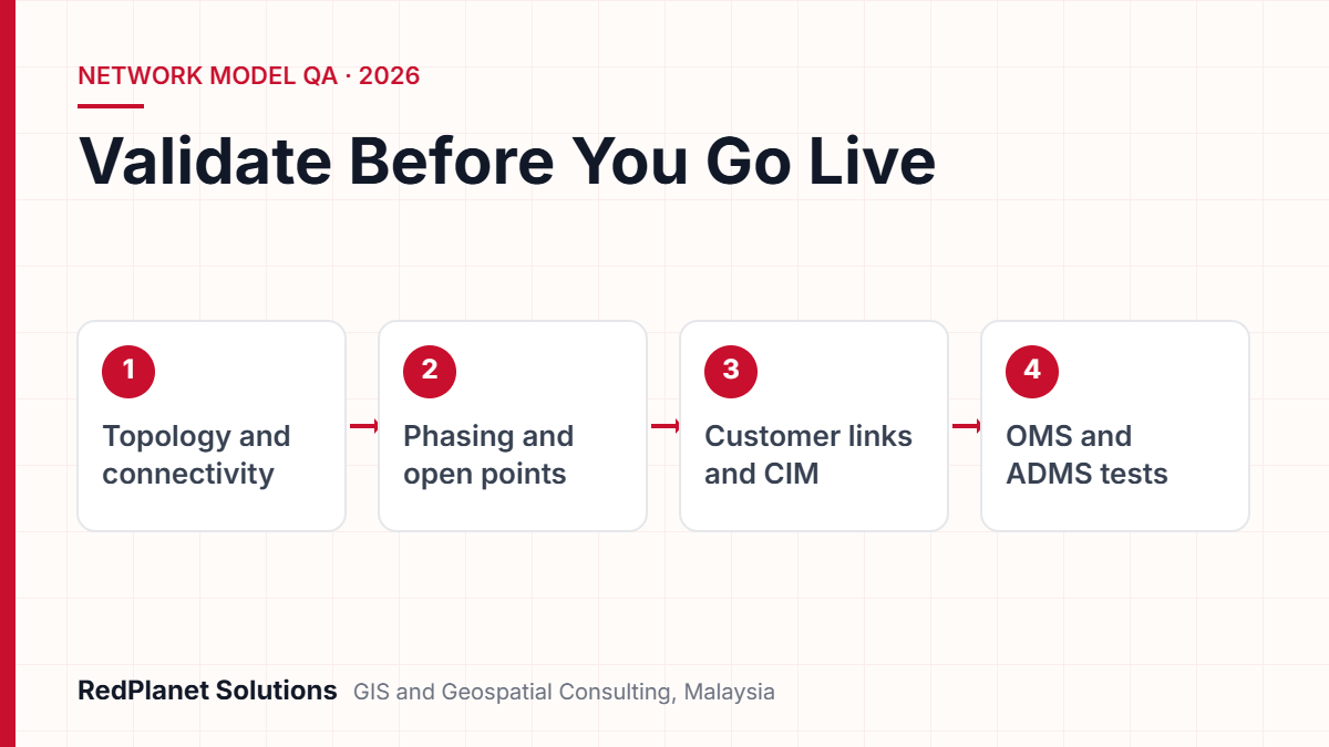
A full checklist moves through four phases, from source data to final acceptance. Each phase has its own exit rules, so teams fix problems where they start.
Electric network model validation checklist
Use these phases in order. Do not start a phase until the one before it meets its exit rules.
Sign-off rules should be measurable and agreed before testing starts. So set targets for trace success, link coverage, missing fields and scenario pass rates. Then decide which issues can go live with a workaround and which must be fixed first.
All targets met and issues are minor
Approve go-live with a logged issue list
Topology or open point failures remain
Hold go-live and fix the source data
Only some regions pass
Go live in phases, region by region
No data upkeep process exists
Agree the process before sign-off
Sign-off should include GIS, network operations, IT and the OMS or ADMS vendor. As a result, no single team owns a risk it cannot see.
What mistakes most often delay network model go-live?
Most delays come from process gaps rather than software. In fact, the same patterns appear in new builds, data migrations and platform upgrades.
Checking a sample only
Samples suit accuracy checks, but link and phase rules must run on the full dataset.
Treating defaults as data
Placeholder ratings pass blank checks, but they give wrong load flow and outage results.
Leaving device states to the end
If open points are fixed late, teams must repeat traces, exports and scenario tests.
Unagreed CIM versions
The GIS exports one version while the vendor expects another, so the load fails late.
No upkeep after go-live
Without as-built updates, quality slips, so the cleanup has to be repeated.
Each mistake has a simple fix: run rules early, define required fields, agree formats in writing and plan upkeep from the start. Platforms such as GE Vernova Smallworld include rule-based checks, but the rules still need owners.
Frequently Asked Questions
What is electric network model validation?
It is the testing of a GIS electric network model before it feeds live systems. Checks cover connections, phases, voltage, device states, customer links, missing fields and data exports. The aim is to prove the model acts like the real network. Then an OMS or ADMS can trace, predict outages and plan switching correctly from day one.
How long does network model validation take before go-live?
It depends on network size, data history and the number of systems that use the model. A recent, well-kept model may need only a few test cycles. However, a model built from old drawings or merged sources usually needs several rounds of fixing and retesting. So plan it as a gated stage with its own schedule, not a final week of checks.
Which IEC standards apply to CIM exports for distribution networks?
The base Common Information Model is IEC 61970-301. IEC 61968-11 adds distribution extensions, and IEC 61968-13 sets profiles for sharing distribution network models. IEC 61970-552 sets the CIMXML file format. Always agree the exact profile version with your OMS or ADMS vendor, because version gaps often cause late load failures.
Why are normally open points so important?
Normally open points set where one feeder ends and the next begins. If one is wrong, the OMS may place the wrong customers under an outage. The ADMS may also produce wrong load flows or switching plans. So check every open point against the approved switching register, and keep normal state apart from the current state.
Can a utility go live with known data issues?
Yes, if the issues are minor, logged and owned. Sign-off rules should state which issues can go live with a workaround, such as a few unverified customer links. But broken topology and wrong open points should normally block go-live, because they affect every trace, prediction and switching plan.
Who should sign off a network model for OMS or ADMS?
Sign-off should include the GIS data owner, network operations, IT and the OMS or ADMS vendor. Each group sees different risks. For example, operators know how the network really runs, while the vendor knows what the system needs. Contact our GIS consultants for an independent readiness review.
How do you keep network model checks working after go-live?
Make the checks a routine, not a one-time milestone. The rules you build for go-live should then keep running on every edit and every export.
Start with topology, then electrical data, then customers and exports. Finally, finish with system tests and measurable sign-off. Also capture new assets when crews install them, so the model keeps pace with the field. That is how utilities protect their OMS and ADMS spend over time.
RedPlanet Solutions supports electric utility GIS programmes in Malaysia, Southeast Asia, India, Australia and the Middle East, from data cleanup to go-live readiness.
Expert Guides
Related GIS Guides
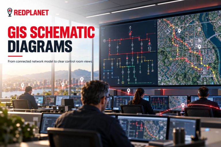 GuideUtility Network Schematic Diagrams: How to Generate a GIS Schematic Diagram From Your Network ModelLearn how to generate a GIS schematic diagram from a connected utility network, covering single line diagrams, data prerequisites and common pitfalls.Read the guide →
 GuideGIS Data Quality Checklist for Utilities: What to Test Before You Accept a DeliverableA GIS data quality checklist for utilities: acceptance criteria, sampling, topology checks, attribute domains and positional accuracy before sign-off.Read the guide →
Get your network model ready for OMS and ADMS
RedPlanet Solutions checks electric network models for utilities, from connection and phase rules to CIM exports and go-live readiness. Talk to us before your next go-live.
Talk To Our GIS Consultants
PK Senthilkumar is CEO of RedPlanet Solutions. His work focuses on GIS consulting, network-based GIS for utilities, enterprise GIS modernisation and practical spatial decision-making for organisations operating across Malaysia, India, Australia and international markets.
About RedPlanet Solutions
RedPlanet Solutions (M) Sdn Bhd is a Malaysia-based GIS consulting and geospatial services company and part of RedPlanet Berhad. The company delivers GIS for electric utilities, spatial data collection, drone surveying, mobile mapping and GIS software development to utilities, government agencies, smart cities and private sector organisations across Southeast Asia, the Middle East, Australia and beyond. RedPlanet works across leading commercial and open-source GIS ecosystems, including GE Vernova Smallworld, Esri, Hexagon, SuperMap, QGIS, GeoServer and FME.